Sulphur Dioxide, SO2
Jim Shorey
SO2 gas is commonly measured by instruments using Ultra Violet UV fluorescence.
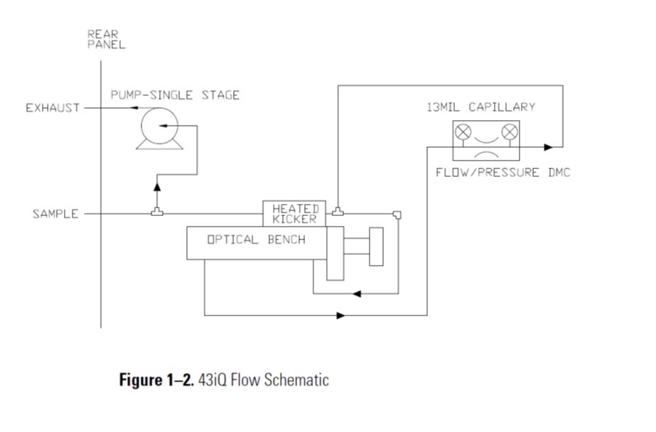
Looking at the Flow Schematic shown below in Figure 1-2, we see the layout of an SO2 Analyzer.
This unit includes an internal Air Sample Pump, which draws Ambient Air into the port labeled as SAMPLE.
The next component is a HEATED KICKER which will remove hydrocarbons from the SO2 Sample Air.
The SO2 Sample Air then enters the OPTICAL BENCH. This Optical Bench chamber has a pulsed Ultra Violet Lamp, which flashes UV light into the Optical Bench. The flashing UV Light excites the SO2 molecules of the Sample Air. As the excited SO2 molecules decay to lower energy state, they emit an Ultra Violet light that is proportional to the SO2 concentration.
The UV light from the excited SO2 molecules is then detected by a photomultiplier tube (PMT), which is a sensitive UV light detector.
The converted SO2 molecules are reported on the analyzer front display as SO2.
The SO2 number is displayed in either Parts Per Billion PPB or Parts Per Million PPM.
The data from the SO2 analyzer can be collected either by Analog Voltage Output or Ethernet Output, to an external datalogger.
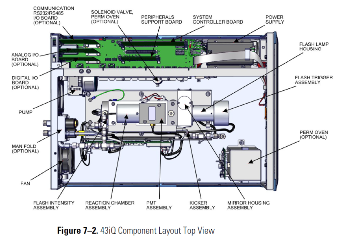
SO2 Analyzer Component Layout