NO-NO2-NOx
Jim Shorey
NO-NO2-NOx gases are commonly measured by instruments using Chemiluminescence.
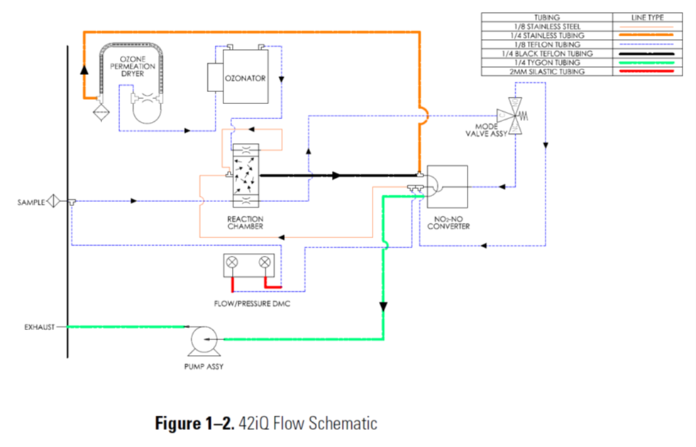
Looking at the Flow Schematic shown below in Figure 1-2, we see the layout of a NOx Analyzer.
This unit includes an internal Air Sample Pump, which draws Ambient Air into the port labeled as SAMPLE. The next component shown as REACTION CHAMBER contains a capillary restrictor which limits the amount of Sample Air. Afterwards, a switching MODE VALVE ASSY directs the Sample Air either to the Reaction Chamber or to the NO2-NO Converter. When the Sample Air is sent to direct to the Reaction Chamber, it mixes with Ozone. Where does the Ozone come from? There is an internal Ozone Generator called OZONATOR shown in the flow diagram. If there is any Nitric Oxide (NO) in the Sample Air, it mixes with the Ozone and is converted to Nitrogen Dioxide (NO2), creating a Chemiluminescent reaction. This reaction produces an Infrared Light emission, which is linearly proportional to the NO concentration. The Infrared Light reaction is detected by a Photomultiplier Tube, which basically is an infrared light detector sensor, that is built into the Reaction Chamber.
That’s how Nitric Oxide (NO) is detected, what about the NO2 and NOx?
When the Mode Valve Assembly switches, it directs Sample Air through the NO2-NO Converter, this is called the NOx mode. The NO2-NO Converter is a steel tube which contains small particles of metal called molybdenum. This metal molybdenum converter is heated to 325 degrees Celsius. When Sample Air passes through this Molybdenum Converter, any NO-NO2 in the Sample Air is converted back into Nitric Oxide (NO) and reported on the analyzer as NOx. The NO and NOx concentrations calculated in the NO and NOx modes are stored in the analyzers memory. The analyzer calculates the difference between the NO and NOx concentrations reports it as the NO2 concentration.
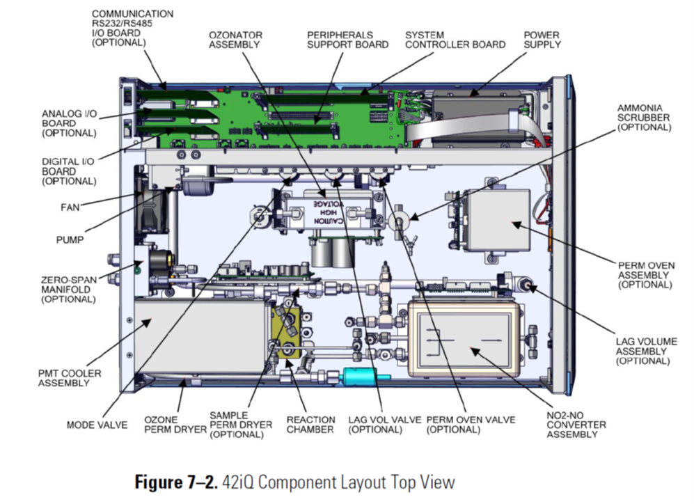
NOx Analyzer Component Layout
The NO-NO2-NOx numbers are displayed in either Parts Per Billion PPB or Parts Per Million PPM.
The data from the NO-NO2-NOx analyzer can be collected either by Analog Voltage Output or Ethernet Output, to an external datalogger.

