Ozone
Jim Shorey
Ozone gas is commonly measured by instruments with UV Photometric Technology
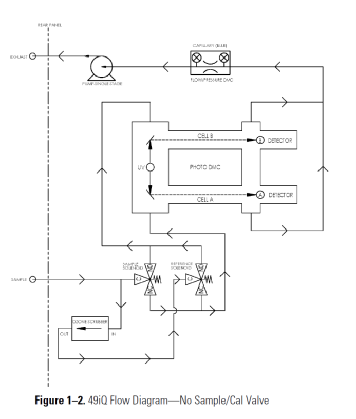
Looking at the Flow Schematic shown below in Figure 1-2, we see the layout of an Ozone Analyzer.
This unit includes an internal Air Sample Pump, which draws Ambient Air into the port labeled SAMPLE.
Once the sample enters the sample bulkhead, it is split into two gas streams. One gas stream flows through an ozone scrubber to become the reference gas. The reference gas then flows to the reference solenoid valve. The air sample gas flows directly to the sample solenoid valve. Both solenoid valves alternate the reference and sample gas streams between cells A and B every 10 seconds. When cell A contains reference gas, cell B contains sample gas and vice versa. The UV light intensities of each cell are measured by detectors A and B. When the solenoid valves switch the reference and sample gas streams to opposite cells, the light intensities are ignored for several seconds to allow the cells to be flushed. The analyzer calculates the ozone concentration for each cell.
The Ozone number is displayed in either Parts Per Billion PPB or Parts Per Million PPM.
The data from the Ozone analyzer can be collected either by Analog Voltage Output or Ethernet Output, to an external datalogger.
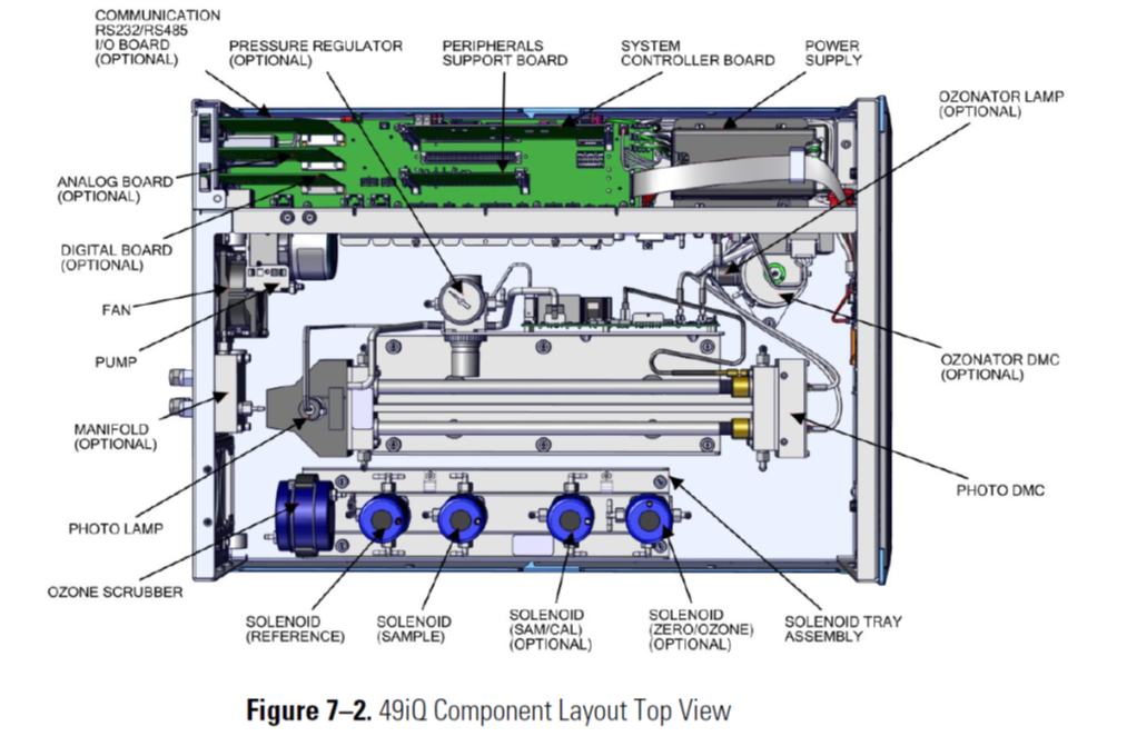
Ozone Analyzer Component Layout