Technology behind the Data – Carbon Monoxide, CO
By: Jim Shorey
CO gas is commonly measured by instruments using Gas Filter Correlation GFC.
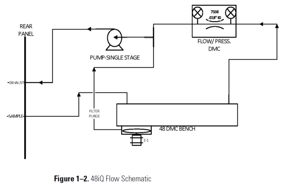
Looking at the Flow Schematic shown below in Figure 1-2, we see the layout of a CO Analyzer.
This unit includes an internal Air Sample Pump, which draws Ambient Air into the port labeled as SAMPLE.
The Carbon Monoxide Analyzer operates on the principle that carbon monoxide (CO) absorbs infrared radiation light at a wavelength of 4.6 microns. A component called the Gas Filter Correlation (GFC) Wheel contains both Nitrogen and Carbon Monoxide, and rotates at high speed on a drive motor.
The GFC Wheel is shown in the diagram below as “FILTER WHEEL”

Gas Filter Correlation (GFC) is an infrared light technique that selectively measures light absorption due to CO by the ratio of sample-absorbed light to a filtered reference measurement. Light from an infrared source (shown as IR SOURCE in the diagram above) passes through the gas filter wheel, which is rotating and alternating between Nitrogen and Carbon Monoxide filled cells (half the wheel is filled with Nitrogen and the other half is filled with Carbon Monoxide).
There are small windows in the wheel which allow light to pass through. Light that passes through the Nitrogen half of the wheel cell is absorbed in the sample gas normally as the Sample Signal. Then light that passes through the Carbon Monoxide half of the wheel cell is blocked where CO absorbs, and is called a Reference.
To summarize, the Infrared Light which passes through the Nitrogen side of the Wheel, is absorbed by any Carbon Monoxide inside the Reaction Cell. The change in Infrared Light is monitored by a Light Detector, which is reported as Carbon Monoxide in either Parts Per Billion PPB or Parts Per Million PPM.
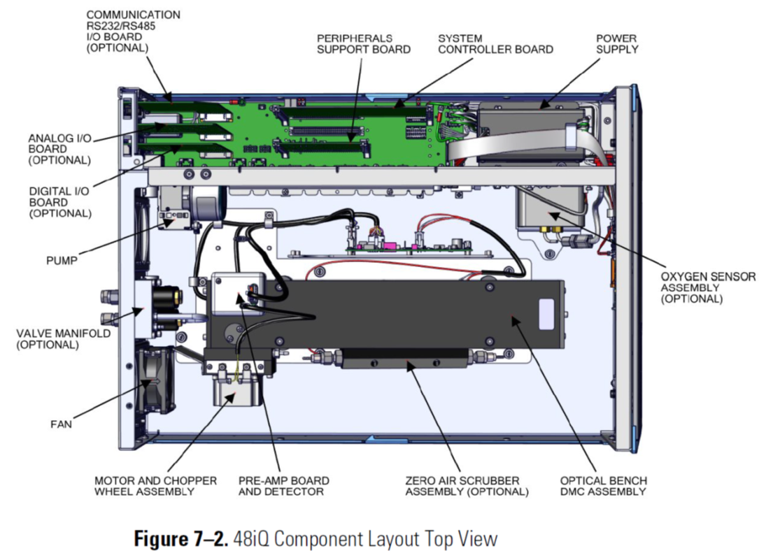
CO Analyzer Component Layout